In the simulation shown above coherent waves emerge from two slits, get superposed with one another, troughs falling on crests and so on and so forth, and interfere. The left edge of the applet shows the slits and the right edge shows a screen that displays bright and dark fringes. The middle part shows the superposing travelling waves from the slits.
In the picture below are shown two paths( in white ), one of complete destructive interference that leads to the center of a black fringe on the screen and another of complete constructive interference that leads to the center of a bright fringe on the screen. There are other paths where the interference is only partially constructive or destructive and these lead to points on the screen where it is neither perfectly black nor perfectly white. Another way of saying this is that the fringes are not sharply cut off between black and white but rather fade into one another.
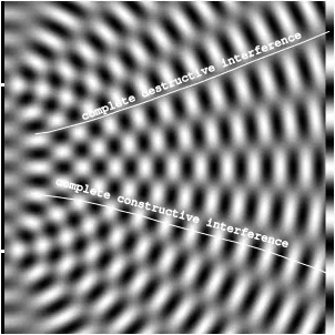
The center of a particular bright or dark fringe on the screen has a particular value for the path difference where is the path length from one slit to that point and is the path length from the other slit to that point. And all along the path that leads to this point the path difference is this value. We know what the path defined by is. It is a hyperbola with the slits as the two focii.
To avoid conditional statements in the fragment shader the applet is implemented as three programs. One for drawing the slits, one for drawing the superposing traveling waves, and one for drawing the screen that displays the fringes. The vertex shader, which simply draws a quad as a strip of two triangles, is common to the three programs.
In the fragment shader for the slits we use the step function. How this works is briefly explained in the random circles post.
#version 300 es
#pragma vscode_glsllint_stage: frag
#ifdef GL_FRAGMENT_PRECISION_HIGH
  precision highp float;
#else
  precision mediump float;
#endif

uniform vec2 u_resolution;
uniform float u_slit_pos;

out vec4 frag_color;
void main( void )
{
  vec2 p = -1.0 + 2.0 * gl_FragCoord.xy / u_resolution.xy;
  float top = step(u_slit_pos - 0.01, p.y) - step(u_slit_pos + 0.01, p.y);
  float bottom = step(-u_slit_pos - 0.01, p.y) - step(-u_slit_pos + 0.01, p.y);
  vec4 col = vec4(1., 1., 1., 1.);
  frag_color = col * top + col * bottom;
};
In the fragment shader for the middle part we see the superposition of the travelling waves expressed as where is the wavelength, the wave velocity, and the time. is the distance of the point from either slit. The wavelength and velocity are conveniently chosen.
#version 300 es
#pragma vscode_glsllint_stage: frag
#ifdef GL_FRAGMENT_PRECISION_HIGH
  precision highp float;
#else
  precision mediump float;
#endif

const float twopi = 6.283185307;

uniform vec2 u_resolution;
uniform float u_time;
uniform float u_slit_pos;
uniform float u_wavelen;

out vec4 frag_color;
void main( void )
{
  vec2 p = -1.0 + 2.0 * gl_FragCoord.xy / u_resolution.xy;
  float c = sin(twopi * (length(p - vec2(-1.0, u_slit_pos)) - 0.05 * u_time) / u_wavelen);
  c += sin(twopi * (length(p - vec2(-1.0, -u_slit_pos)) - 0.05 * u_time) / u_wavelen);
  c = (c + 2.0) * 0.25;
  frag_color = vec4(c, c, c, 1.0);
};
The fragment shader for the screen calculates the intensity of the superposition of the waves from the two slits. It can be shown that the intensity is proportional to where is the phase difference of the superposing waves.
#version 300 es
#pragma vscode_glsllint_stage: frag
#ifdef GL_FRAGMENT_PRECISION_HIGH
  precision highp float;
#else
  precision mediump float;
#endif

const float twopi = 6.283185307;

uniform vec2 u_resolution;
uniform float u_slit_pos;
uniform float u_wavelen;

out vec4 frag_color;
void main( void )
{
  vec2 p = -1.0 + 2.0 * gl_FragCoord.xy / u_resolution.xy;
  float r2 = length(vec2(1.95, p.y - u_slit_pos));
  float r1 = length(vec2(1.95, p.y + u_slit_pos));
  float phi = twopi * (r2 - r1) / u_wavelen;
  float c = cos(phi / 2.0);
  float c2 = c * c;
  frag_color = vec4(c2, c2, c2, 1.0);
};
Here is the complete code.